- This topic is empty.
-
AuthorPosts
-
2026-10-19 at 5:00 pm #12594
An integrated circuit may operate normally at room temperature but develop intermittent faults when exposed to high or low temperatures. Communication errors, unstable output signals, timing deviations, and unexpected changes in electrical parameters can appear only under specific thermal conditions.
For semiconductor engineers, reproducing these faults is often the first step toward understanding their cause.
A Temperature Forcing System provides a practical way to investigate temperature-dependent device behavior by directing controlled hot or cold airflow onto a specific device under test (DUT). Instead of conditioning an entire chamber, engineers can apply localized thermal stimulation while monitoring the device’s electrical or functional response.
This approach is particularly useful during IC characterization, semiconductor failure analysis, component verification, and electronic troubleshooting.
1. Why Do Some IC Failures Appear Only at Certain Temperatures?
Semiconductor devices do not necessarily maintain identical electrical characteristics across their entire operating temperature range.
Temperature can influence semiconductor carrier behavior, transistor characteristics, leakage current, switching performance, timing margins, and other electrical parameters. The direction and magnitude of these changes depend on the device technology, circuit design, operating conditions, and package.
In digital systems, a temperature-related change in timing behavior may contribute to a functional failure when the available timing margin is limited. In analog circuits, temperature-dependent parameter drift may affect accuracy, bias conditions, or signal stability.
Power semiconductor devices introduce additional considerations because their electrical behavior and heat dissipation can interact with the surrounding thermal environment.
Other failures may be associated with package materials, solder joints, interconnections, or differences in thermal expansion. However, a fault that appears at a particular temperature does not automatically establish its physical root cause.
Engineers need a controlled way to reproduce the observed behavior and collect evidence.
2. Why Localized Thermal Testing Can Be Useful
A conventional environmental test chamber controls conditions throughout an enclosed working space. This is appropriate when the complete product or assembly must experience a defined environmental profile.
However, when investigating a suspected temperature-sensitive component on a circuit board, conditioning the entire assembly may introduce unnecessary thermal exposure to other components and connected equipment.
A Temperature Forcing System takes a different approach. It delivers controlled hot or cold airflow directly to a selected test location.
This localized method can help engineers:
-
Investigate a suspected IC without conditioning the entire test setup.
-
Observe changes in electrical parameters as the target temperature changes.
-
Reproduce intermittent faults under controlled thermal conditions.
-
Compare device behavior at selected temperature points.
-
Perform thermal stimulation while the DUT remains connected to suitable test instruments.
-
Investigate whether an observed fault is associated with the target component’s temperature response.
The objective is not to prove the root cause from temperature exposure alone. It is to create a more controlled diagnostic condition that helps engineers narrow down possible causes.
3. A Practical Workflow for Temperature-Sensitive IC Failure Analysis
A repeatable test procedure is essential when using localized thermal stimulation to investigate semiconductor faults.
Step 1: Establish the Baseline at Room Temperature
Before applying thermal stress, verify the DUT’s normal operating behavior.
Record relevant electrical parameters, functional outputs, communication status, power consumption, and any available diagnostic information. The specific measurements depend on the device and the suspected failure mechanism.
This baseline provides a reference for comparison when the temperature changes.
Step 2: Define the Temperature Test Profile
Determine the temperature points or transitions required to reproduce the suspected fault.
The profile should be based on the device’s specifications, the investigation objective, and applicable test requirements. Avoid assuming that the widest possible temperature range is automatically the most appropriate.
For example, an investigation may begin by comparing normal operation at room temperature with behavior at selected high- and low-temperature conditions.
If the failure occurs only during a transition, the transition profile and the timing of the measurements may also be important.
Step 3: Direct Controlled Airflow Toward the Target Device
Position the forcing nozzle so that the conditioned airflow is directed toward the intended test location.
Nozzle distance, orientation, airflow rate, surrounding components, and the geometry of the DUT can influence the resulting temperature distribution.
For circuit boards containing multiple closely spaced components, it is important to consider how much thermal exposure reaches neighboring devices. Localized airflow does not guarantee that only one component changes temperature.
A suitable setup should therefore be verified using appropriate temperature measurements rather than relying solely on the system’s displayed setpoint.
Step 4: Monitor the DUT During Temperature Changes
Observe the device’s electrical or functional behavior as the temperature changes.
Depending on the application, relevant measurements may include:
-
Supply current and power consumption
-
Output voltage or signal amplitude
-
Switching behavior and timing margins
-
Communication stability
-
Functional test results
-
Error codes or intermittent fault indicators
Time-correlated temperature and electrical data can help identify whether the abnormal behavior consistently occurs under particular thermal conditions.
The measurement system must also be suitable for the electrical signals and operating environment involved.
Step 5: Repeat the Test to Check Reproducibility
A single failure event may not provide enough evidence to establish a reliable relationship between temperature and device behavior.
Repeat the relevant test sequence using consistent setup conditions. Record the temperature profile, airflow configuration, DUT position, measurement locations, and observed response.
If the fault repeatedly appears under similar conditions and disappears when the temperature returns to a different range, the evidence for temperature-dependent behavior becomes stronger.
Further electrical analysis, component substitution, microscopy, or other failure-analysis techniques may still be necessary to determine the underlying mechanism.
4. Why Temperature Response at the DUT Matters
One important consideration in localized thermal testing is the difference between the air temperature and the actual temperature of the device.
A forcing system controls the temperature of the supplied airflow, but the DUT’s thermal response also depends on its package, dimensions, thermal mass, mounting arrangement, surface characteristics, and heat generation.
A small component may respond differently from a larger package. A device operating under electrical load may also behave differently from one that is unpowered.
For this reason, engineers should distinguish among three measurements:
System temperature: The temperature reported by the forcing system’s control or monitoring arrangement.
Local airflow temperature: The temperature of the air near the target location.
DUT temperature: The measured or estimated temperature of the component being evaluated.
These values are related but should not automatically be treated as identical.
Where the test objective depends on the component’s actual temperature, appropriate sensor placement and a validated measurement method are important. The measurement setup should also avoid disturbing the airflow or the electrical test configuration.
This distinction helps prevent engineers from attributing a failure to an incorrect temperature threshold simply because the system setpoint was used as a substitute for the DUT temperature.
5. Temperature Forcing System vs. Environmental Test Chamber
The two systems support different testing objectives.
A Temperature Forcing System is generally suited to localized thermal stimulation of a component or selected test area. It can be useful when engineers need to observe the response of an IC while connected to electrical test equipment or when the entire assembly does not need to be conditioned.
An environmental test chamber is more appropriate when the complete product, assembly, or sample population must experience a controlled environmental condition. Depending on its configuration, the chamber may support temperature exposure, temperature cycling, humidity testing, or other environmental reliability evaluations.
The choice depends on the diagnostic question.
If the objective is to investigate how a particular IC responds to localized temperature changes, a forcing system may provide a more direct test arrangement.
If the objective is to evaluate the environmental performance of a complete electronic assembly, a chamber may be more appropriate.
Some testing programs require both approaches at different stages of product development and reliability verification.
6. What Should Engineers Consider When Selecting a Temperature Forcing System?
Selecting a system involves more than checking its minimum and maximum temperature specifications.
The following factors should be considered.
Temperature Range and Transition Performance
Confirm the required operating temperatures and the relevant transition interval. If rapid changes are necessary, verify the specified transition time and the conditions under which it applies.
Equipment transition performance should not be confused with the time required for a DUT to reach its target temperature.
Airflow Adjustment
The airflow rate and nozzle configuration affect how conditioned air reaches the test location.
An appropriate configuration should provide sufficient thermal stimulation without unnecessarily disturbing neighboring components or the measurement arrangement.
Nozzle Positioning
Flexible positioning can help engineers direct airflow toward different devices, packages, or test points.
The available positioning range and nozzle options should match the dimensions and layout of the DUT.
Temperature Measurement and Feedback
Determine which sensor types and measurement locations are required. External temperature feedback may be important when the test objective depends on the temperature at a specific point.
The measurement method should be validated for the DUT and the intended temperature profile.
Integration With Electrical Test Equipment
Consider the physical arrangement of probes, cables, fixtures, power supplies, and measurement instruments.
The system should fit the test workflow while maintaining appropriate electrical safety and measurement integrity.
Test Repeatability and Documentation
The system should support a defined procedure for temperature profiles, airflow configuration, sensor placement, and test observations.
Consistent setup and traceable records are important when comparing devices or investigating intermittent faults.
7. KOMEG Temperature Forcing System for IC and Electronic Testing
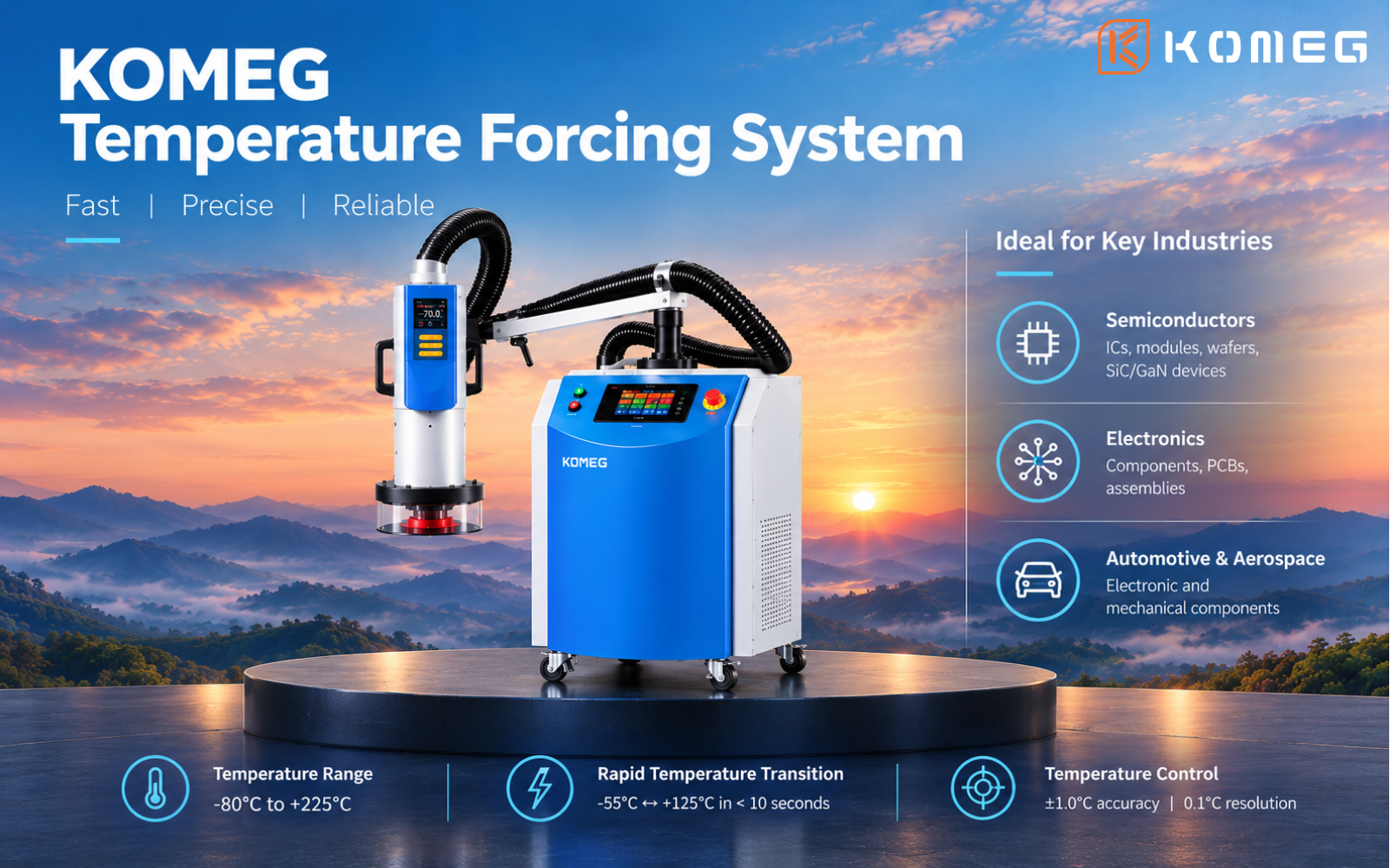
KOMEG’s Temperature Forcing System is designed to deliver controlled hot or cold airflow directly to the device under test.
Its key specifications include:
-
Operating temperature range: -80°C to +225°C
-
Bidirectional temperature transition time: under 10 seconds between -55°C and +125°C
-
Temperature control accuracy: ±1.0°C
-
Temperature setpoint resolution: 0.1°C
-
Adjustable airflow: 5–24 SCFM
-
Flexible nozzle positioning for localized thermal stimulation
-
Support for T-type and K-type thermocouples and RTD sensors for external temperature feedback
The transition-time specification applies to the stated -55°C to +125°C interval and should not be interpreted as a guarantee that every DUT reaches its target temperature within 10 seconds.
Actual component temperature response depends on the test setup, package characteristics, thermal mass, airflow, nozzle position, and measurement arrangement.
For engineers investigating temperature-sensitive IC behavior, these capabilities can support controlled thermal stimulation without requiring the entire test setup to be conditioned by a conventional environmental chamber.
The appropriate configuration should be selected according to the DUT, test profile, measurement requirements, and laboratory workflow.
Frequently Asked Questions
What is a Temperature Forcing System used for in IC testing?
A Temperature Forcing System delivers controlled hot or cold airflow directly to a semiconductor device or selected test location. It can support IC characterization, temperature-dependent electrical testing, and thermal-related failure analysis.
Can a Temperature Forcing System help reproduce intermittent chip failures?
It can help engineers investigate faults that appear under specific thermal conditions. By applying controlled airflow and monitoring electrical or functional behavior, engineers can determine whether the fault is reproducibly associated with temperature changes. Additional analysis may be required to identify the physical root cause.
Does the displayed air temperature equal the IC temperature?
Not necessarily. The actual IC temperature depends on package design, thermal mass, heat generation, airflow, nozzle position, and other factors. Appropriate temperature measurement is important when the DUT’s actual temperature is central to the test objective.
Can a Temperature Forcing System replace a temperature test chamber?
Not for every application. A forcing system focuses on a selected component or area, while a conventional environmental chamber conditions a larger enclosed space. The appropriate solution depends on whether the test requires localized thermal stimulation or whole-product environmental exposure.
How quickly can the KOMEG Temperature Forcing System change temperature?
The system supports bidirectional transitions between -55°C and +125°C in under 10 seconds. This is the specified equipment transition performance for that interval, not a universal guarantee of DUT temperature response.
Temperature-sensitive IC failures can be difficult to reproduce because they may occur only under particular thermal conditions or operating states.
A Temperature Forcing System provides a targeted way to apply controlled hot or cold airflow while engineers monitor the DUT’s electrical and functional behavior. When combined with suitable temperature measurement, a consistent test setup, and repeatable procedures, localized thermal testing can help narrow down potential causes and support semiconductor failure analysis.
KOMEG’s Temperature Forcing System supports localized thermal testing across a wide operating range and can be considered for semiconductor, electronic component, and other temperature-dependent testing applications.
To evaluate the system for a specific IC or electronic test, engineers should define the required temperature profile, transition time, DUT characteristics, airflow arrangement, sensor requirements, and test-instrument configuration.
Explore the KOMEG Temperature Forcing System:
https://www.komegtek.com/product/temperature-forcing-system/https://www.komegtek.com/product/temperature-forcing-system/
OMEG Temperature Forcing System -
-
AuthorPosts

- You must be logged in to reply to this topic.