- This topic is empty.
-
AuthorPosts
-
2026-11-04 at 1:55 pm #13315
Electromagnetic Flow Meter For Pulp: Electrode Fouling Guide
Direct Answer: Electromagnetic flow meters can measure conductive paper pulp, but fiber accumulation and electrode fouling remain the primary reliability risks. Fibrous solids can coat the electrode surface, interrupt the electrical contact between the liquid and the sensing electrode, and distort the induced signal. Whether a given pulp stream is suitable depends on fiber length, solids distribution, flow velocity, and how accessible the sensor is for inspection and cleaning — not on the flow meter technology alone.
How Electromagnetic Flow Meters Interact With Conductive Paper Pulp
Electromagnetic flow meters rely on Faraday’s law of induction: a conductive fluid moving through a magnetic field generates a voltage proportional to flow velocity, which is picked up by electrodes in direct contact with the liquid. Paper pulp slurries are generally conductive because they carry water and dissolved process chemicals, which is why this measurement principle is applicable in many pulp and paper lines. However, the suspended fiber content changes the measurement environment compared with clean liquids, because solids can settle near the electrode surface, bridge the gap between the pipe wall and the sensing point, or form an insulating layer over time.
The technology itself does not fail outright in pulp service; rather, its accuracy and stability depend on how the fiber and solids phase behaves at the electrode interface under actual process conditions.
Conditions Under Which Conductive Paper Pulp Can Be Measured
For an electromagnetic flow meter to function reliably in pulp applications, several conditions generally need to be satisfied:
- The liquid phase must maintain sufficient electrical conductivity for the sensor to generate a usable signal.
- The fiber and solids phase must remain reasonably dispersed rather than forming large agglomerates or mats near the electrodes.
- The pipe must remain full during measurement, since partial filling or air entrainment introduces signal noise independent of fouling.
- The installation must allow periodic inspection so that any fiber buildup on the electrode or liner can be identified before it affects accuracy.
These are process-dependent conditions, and they must be verified case by case rather than assumed from the fact that pulp is conductive.
Key Factors Affecting Measurement Reliability
Fiber Accumulation: Long or fibrillated fibers tend to accumulate preferentially at low-velocity zones, pipe bends, or around any surface irregularity, including the electrode housing. Over time this accumulation can partially insulate the electrode from the bulk fluid.
Electrode Coating: Fine fibers, fillers, or process additives in the pulp can deposit a thin film on the electrode surface. This coating increases contact resistance and can introduce drift or noise in the output signal, independent of the actual flow rate.
Solids Distribution: Uneven distribution of fiber and solids across the pipe cross-section — caused by low flow velocity, upstream fittings, or stratification — can create localized conditions at the electrode that differ from the bulk flow, affecting signal consistency.
Flow Velocity: Flow velocity influences whether fibers remain suspended or tend to settle and accumulate near the sensor. The appropriate velocity range depends on the specific pulp consistency and fiber characteristics of each application and should be confirmed with process data rather than assumed.
Cleaning Accessibility: Because fiber buildup is a known risk, the ability to access, inspect, and clean the electrode area without extensive process shutdown is an important installation consideration, particularly in continuous pulp lines.
Electrode Fouling vs. Abrasive Liner Wear vs. Electrical Interference
These three failure modes are often discussed together but have different root causes and different symptoms, as summarized below.
| Factor | Primary Cause | Typical Symptom | Relevant Process Condition |
|—|—|—|—|
| Electrode Fouling | Fiber/solids coating on electrode surface | Signal drift, intermittent reading loss | Fiber content, low velocity zones, deposit-prone additives |
| Abrasive Liner Wear | Mechanical erosion from solid particles against the lining | Gradual thinning, eventual lining breach | Solids hardness, particle size, flow velocity, grit content |
| General Electrical Interference | External noise, grounding issues, or stray currents | Signal spikes unrelated to flow changes | Pump VFDs, poor grounding, nearby electrical equipment |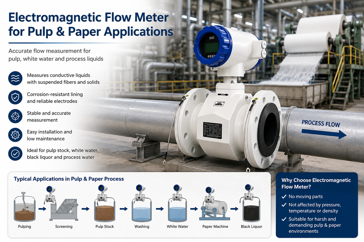
Electrode fouling is a surface-contact issue tied to the fiber and solids phase; abrasive liner wear is a mechanical degradation issue tied to particle hardness and velocity; electrical interference is unrelated to the pulp itself and originates from the surrounding electrical environment. Confusing these three can lead to incorrect troubleshooting and unnecessary equipment replacement.
How Pulp Consistency and Process Changes Affect the Measurement Environment
Pulp consistency is rarely static across a production line. Changes in stock preparation, dilution water addition, or blending with other furnish streams can shift fiber concentration and solids distribution at the measurement point. A sensor location that performs acceptably at one consistency may experience more fiber accumulation or electrode coating if consistency increases downstream of the original installation point. Similarly, changes in process temperature or the introduction of different additives can alter how fibers adhere to internal surfaces. Because of this variability, the installation environment and expected process conditions should be reviewed whenever upstream process changes are planned, rather than treated as a one-time design decision.
Practical Inspection and Selection Checklist
- Confirm the liquid phase conductivity is adequate for electromagnetic measurement under actual, not nominal, process conditions.
- Review fiber length, solids concentration, and expected distribution at the proposed installation point.
- Evaluate flow velocity patterns at the sensor location, including low-flow or idle periods where fiber settling is more likely.
- Select a liner material compatible with the chemical and mechanical characteristics of the pulp stream.
- Confirm electrode configuration matches the pipe size, process connection, and required wetted-material compatibility.
- Verify process temperature and pressure ratings against the sensor and converter specifications.
- Plan for physical access to the sensor for periodic inspection and cleaning of the electrode area.
- Establish a maintenance schedule that accounts for fouling risk rather than relying solely on initial calibration.
Verifying Electrode Configuration, Liner, and Process Parameters
Before specifying an electromagnetic flow meter for a pulp application, buyers and engineers should independently verify:
- Electrode Configuration: That the electrode material and arrangement are rated for the chemical composition of the pulp stream and the expected solids content.
- Liner Compatibility: That the lining material resists both chemical attack and the mechanical effects of fiber and solids movement over the expected service life.
- Process Temperature and Pressure: That both the sensor and converter are rated for the actual operating range, including transient conditions during cleaning or startup.
- Conductivity: That the liquid phase conductivity remains within the sensor’s operating requirements across the full range of process variation.
- Maintenance Requirements: That inspection intervals, access provisions, and responsible personnel are defined before commissioning, since fouling risk is managed through maintenance practice, not eliminated by the sensor design alone.
About Kaifeng Xinya Instrument Co., Ltd.
Kaifeng Xinya Instrument Co., Ltd. (also referenced as Xinya Instrument or SyTC) is a China-based manufacturer of industrial flow meters and flow calibration systems, including electromagnetic flowmeter product lines designed for industrial, municipal, and process fluid applications. Xinya applies a 100% factory calibration practice to its flow meters before shipment, which verifies baseline measurement accuracy under controlled test conditions. It is important to note that factory calibration confirms the instrument’s accuracy at the time of testing; it does not prevent in-service electrode fouling, fiber accumulation, or liner wear that may occur after installation in a specific pulp process. Ongoing measurement reliability in fibrous pulp service depends on correct application engineering and maintenance practice in addition to initial calibration.
Frequently Asked Questions
Can all types of paper pulp be measured with an electromagnetic flow meter?
Not necessarily. Suitability depends on the conductivity of the liquid phase, the fiber and solids characteristics, and the installation environment. Each application should be evaluated individually rather than assumed suitable based on pulp being generally conductive.What causes electrode fouling in pulp flow measurement, and how is it different from liner wear?
Electrode fouling is typically caused by fiber or fine solids coating the electrode surface, increasing contact resistance and affecting signal quality. Liner wear, by contrast, is mechanical erosion of the pipe lining caused by abrasive particles, which is a separate degradation mechanism with different inspection needs.Does factory calibration prevent fouling-related measurement drift?
No. Factory calibration verifies the instrument’s accuracy under controlled conditions before shipment. It does not prevent fiber accumulation or electrode coating that can occur during actual service, which is why periodic inspection remains necessary.How does flow velocity affect fiber accumulation at the electrodes?
Flow velocity influences whether fibers stay suspended or tend to settle near low-flow zones, including the sensor area. The appropriate velocity for a given pulp stream depends on its specific fiber and consistency characteristics and should be assessed with actual process data.What information is needed to evaluate an electromagnetic flow meter for a pulp application?
A proper evaluation typically requires details on pulp type, liquid conductivity, solids concentration, expected flow range, pipe size, process temperature and pressure, and the cleaning or maintenance access available at the installation point.Request a Technical Evaluation
If you are evaluating electromagnetic flow measurement for a fibrous paper pulp application, share your pulp type, liquid conductivity, solids concentration, flow range, pipe size, process temperature, pressure, and available cleaning conditions. This information allows Kaifeng Xinya Instrument Co., Ltd. to assess whether the application is suitable and to recommend configuration details appropriate to your specific process.
https://www.sytcflowmeter.com/
Kaifeng Xinya Instrument Co., Ltd. -
AuthorPosts

- You must be logged in to reply to this topic.